A Wood Laser Cutter Fixture for RC Airplane Parts
A wood laser cutter with a maximum work length of 30"(762mm) was required to cut longer lengths of balsa and ply. 36"(914.4mm) and 48"(1219.2mm) are standard lengths of material available from material suppliers. The Boss LS-1630 laser cutter has a work envelope of 400mm x 750mm (15.75" x29.53") .
The above image of the wood laser cutter fixture is interactive. You can use your mouse wheel to zoom in and out and if you press the shift key and the wheel you can rotate the image.
To return the image to the start point click on the house symbol in the top right hand corner.
The icons at the bottom of the screen have various effects but the "explode" icon is very spectacular!
The icon at the extreme right will give a full screen image.
All of this is available as I used Fusion 360 3D software to design this fixture.
PAGE CONTENTS
Features of the Wood Laser Cutter Fixture.

Misumi 20 X 20 aluminum extrusions were used to build the fixture.
This makes for a very flexible layout and all the various components can easily be adjusted for position.
Previous experience with laser cutting of thin balsa sheets indicated that a method of holding down the material, during cutting was desirable.
Another advantage of this fixture is that no "edge finding" procedure is required, other than for the first sheet. All subsequent sheets will be located in exactly the correct position for cutting.
The drawing shown here is the General Assembly of the wood laser cutter fixture(# E20217GA7). If you click on the image, you will see a larger image . There is a parts list in the top left hand corner where all the parts are listed.
The item numbers are referred to below, in some of the headings.

Specifications
- Size of opening in Boss Laser-29 9/16" x 15 3/4" (750mm x 400mm)
- Maximum X axis laser travel- 29 9/16" (750mm)
- Minimum material thickness to be cut-0.031" (1.6mm)
- Maximum material thickness to be cut-0.25" (0.8mm)
- Minimum material width-3" (76.2mm)
- Maximum material width-6" (152.4mm)
- Maximum material length-48" (1219.2mm)
Laser Machine Requirements

A wood laser cutter, other than the Boss LS-1630 could be accommodated but it must be possible to allow longer material to be used.
On the boss laser, door are included on both ends of the X axis. This allows the fixture to extend as well as the material.
The material support slats are removed and the fixture is clamped into the resulting opening.
If you need help in adapting this design, to your laser cutter, then please contact us and we will be happy to help.
End Stop Assembly (Item13)

This assembly is a 3D printed part. There is just one unit required per fixture.
It is used at the indexed position of the 48" long sheets.
For more details of 3D printed parts, click here.
End Stop Assembly-Rotatable (Item 15)


This assembly is used to locate the material sheet in the first position. After the laser cutting cycle is complete, the stop is rotated down 90 degrees, to allow the material to be moved to the final position.
Note that the friction can be adjusted by the "tightness" of the socket head cap screw. The up and down stops are built in.
Most parts are 3D printed, Click here for more information on printed parts.
Two assemblies are required per fixture.
Material Support Assembly (Item 9)

The Material Support Assembly is used to support the balsa or ply sheets, during the cutting process.
This item is made of cold rolled steel. Quantity needed is 12 per fixture.
They can be made at a local machine shop or they can be made in a home workshop. A good power jig saw is required to cut the shape from 0.09" thick steel and a sold vice can be used to make the 90 degree bend.
A drill press is a great asset to assist in all drilling operations.
Click here for more information and PDF files of manufactured parts.
Clamp Block Assembly (Item 10)


This unit ensures that the material being cut is pressed flat along the edges. This is particularly important on the thinner materials. There are 4 assemblies per fixture.
The plastic base (3D Printed) has the steel dowel assembly, sliding vertically, so no adjustment is required.
The steel dowel assembly is made from standard dowels and cold rolled steel. It can be produced in a home workshop or you may prefer to use a local machine shop.
Material Location Assembly (Item 14)

This is a 3D printed part and 6 assemblies are needed for each wood laser cutter fixture.
The vertical face locates the material in the first cutting position and also in the second position.
Programming Notes

The first position in the image here shows a laser cutting program in a 2D Cad system. This shows a typical 36"x6" balsa sheet of components.
Using a 2D CAD program of your choice draw a line 27" from the left hand end of the material.
Make a copy of this.
On copy 1 delete all the lines on the right hand side. (See "Program A" on image).
On copy 2 delete all the lines on the left hand side. (See "Program B" on image.)
Load programs into the wood laser cutter.
Place material into position in fixture.
Laser cut Program A.
Rotate Stop down (Item 15).
Move material to second Stop (Item 15)
Laser cut Program B.
Fixture Set-Up & System Operation.


Set-up the wood laser cutter fixture to the dimensions shown in Image 'A'. for 6" wide sheets. The stops are positioned for 36" and 48" long sheets. If narrower widths of material are to be cut then move the longitudinal rail (Item12) by slacking off the screws in the corner brackets (Item 8) and sliding the whole assembly back.
It maybe best to slide up to a piece of the material to be cut and let the location parts (Item14) to just touch. I found that so called 6" wide balsa was actually 5.9" wide! Fortunately all of the batch was the same width.
The minimum width that the fixture will accommodate is 3" (See Image 'C' above).
Once the fixture is set-up, the sequence of operation is as follows-
- Place the sheet of material to the initial position (As shown in Image 'A')
- Cut using the first program.
- Rotate the stop 'down' (Item 15 #1)
- Slide the material to the left until it touches the second stop (Item 15 #2)
- Cut using the second program.
- Remove material.
- Rotate first stop 'up' (Item 15 #1)
- Repeat.
Note that if 48" long material is being used then second stop (Item15 #2) is permanently left in the 'Down' position and the material is moved to the End Stop (Item 13), in step 4 above.
Buy Plans of the Engineering package.
The package consists of 23 PDF files, that include 8 general assembly drawings and all the sub assembly drawings.
They can all be printed out at 8.5" x 11" sheets.
If you need differences to the design of this wood laser cutter fixture, to suit your particular laser cutting machine, then please contact me and I will try and help.
To order the package, just click on the PayPal "Buy Now" button to order, and I will send you the PDF package.
Note that you do not need a PayPal account and you can use your favorite credit card.
Photo Gallery
The prototype wood laser cutter fixture was built using all manufactured parts (i.e. no 3D printed parts). The use of some 3D printed parts significantly reduces the cost.
Some parts, like the material support assemblies (Item 9), need to be made of steel as they will be contacted by the laser beam and plastic parts would surely melt!
The clap block dowel assembly (Part of Item10) are made of steel, to provide weight to clamp the thinner materials down.
If you look at pictures 5,7 and 8 you can see how well the fixture works in lining up the first and second cuts.


Bill of Material (BOM).

The BOM is just one page, but includes all the items needed for one assembly.
Part numbers are included as well as the price and also a link to the appropriate page on the supplier's web site.
3D Printed Parts.
Many of the components of the wood laser cutter fixture, lend themselves to 3D printing and this process certainly is cost effective.
I have had success with Shapeways and find their automatic process a teal time saver,
You can order the parts directly from Shapeways by clicking on the images below.
The material used is a very hard white nylon, that is very durable.
Clamp Block Base-4 Req'd.
End Stop 2-1 Req'd
Location Angle-6 Req'd
End Stop Bracket-2 Req'd.
End Stop- 2-Req'd.
Manufactured Parts.
There are only 2 parts on the wood laser cutter fixture that are made of steel and could be made by a local machine shop.
The material support (12 Required) is made of steel, because it is in the direct path of the laser and the clamp block ( 4 Required) needs the weight of steel to hold the material being cut down.
I am waiting for quotations from a few suppliers and will post the information here, when available.


Get Gloster Gladiator Profile eBook Free

Don't worry your e-mail address is totally secure.


Recent Articles
-
The Bristol Bulldog vintage biplane, of the RAF, in 1930
May 22, 23 10:47 AM
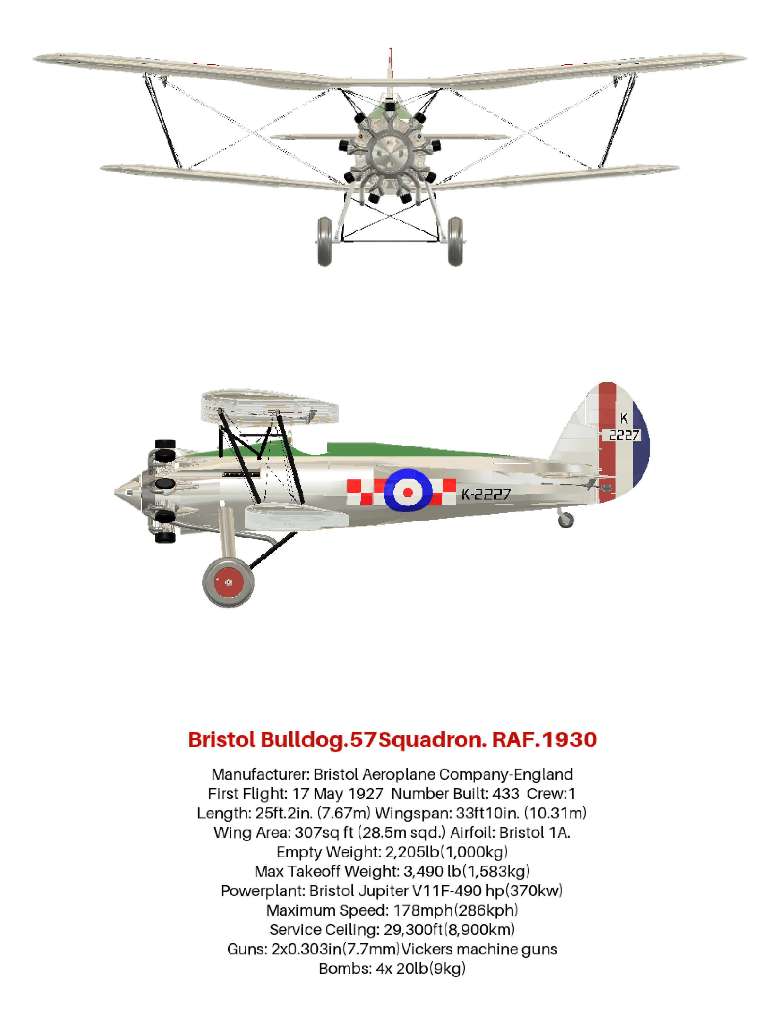 How the aviation art, of the Bristol Bulldog vintage biplane, was produced, using 3D software. Included are photos and links to many aviation gifts, from Zazzle
 -
Aviation gifts For All Airplane Lovers
Apr 20, 23 11:12 AM
 Aviation gifts for every occasion. Give your airplane fanatic friends and relatives the present they will really appreciate! Can be customized to make it truly unique.
 -
RC Retractable Landing Gear: The JP Hobby ER-005 Metal Strut Set.
Dec 19, 22 01:55 PM
 Full details of RC retractable landing gear. For models up to 6 Kg (13.2 lbs). Steerable nose wheel and sequencer for gear doors and brakes. For grass strips.
 -
FLEX RV-8 70CC FLS:ARF and ARFSV.
Nov 02, 22 02:45 PM
 The Flex RV-8 70cc, 35% Scale, 3D RC Airplane. Super lightweight and gas or electric power. Very complete and fast assembly.