Gloster Gladiator RC Plans at 1/5 Full Size
The Gloster Gladiator is CAD designed and takes up 9 sheets,36"x75". Each sheet is described in detail with design intent explained.
Sheet 1-Fuselage Side View of the Gloster Gladiator

Basic Fuselage Construction
The 1/4" thick balsa sheet sides are completed with 1/4"square longerons and uprights. 2 identical sides are constructed and then joined into the basic box section (Over the plan view on sheet 2).
Formers are added and forward areas are sheeted with 1/8" thick balsa.
The rear outer longerons are 1/8" diameter dowels.(Strong and light and closer to scale shape than square balsa or hardwood)
Note that there is room for a full width cockpit and you can build a sliding canopy.(Details on sheet 3)
Electrical Power Installation
This view shows the E-Flite Power 160 installation and note that the batteries can be placed inside the cowl. or under the upper hatch that runs from former C1 to D2.
The Horizon Hobbies motor mount has plywood trays mounted top and bottom for the 2 -5S 18.5V 5000mAh Lipos. The OS ESC is also mounted here.
Cowl construction
The cowl construction is described in detail on this page.
Balsa and ply formers are planked with 3/16"x 4"wide balsa. Spraying with Windex, on the outside, makes this task a little easier.
The cowl is split and one half is removable, giving access to the batteries that are held in place with Velcro straps.
Rigging
The top wing is at 2 degrees incidence and the bottom wing is at 1.5 degrees. The theory is that the bottom wing stalls first while the top wing is still giving lift. ( Who knows if this happens, but I have used this set-up previously, with success.)
The tailplane is at 0 degrees,
Note that at the CG position, in the top wing, an anchor nut is built in.(See sheet4). A threaded hook can be inserted and the complete Gloster Gladiator can be suspended from this point.
The model can now be balanced fore and aft as well as laterally.
Rear Fuselage
The servos can be mounted in the rear or in the forward fuselage. I chose to use the rear location and use the much shorter pushrods.
The rudder and fin are built on a 1/16" thick balsa core, flat on the plans, with ribs added, then removed from the building board and opposite side ribs are then added.
Robart hinges are used and the whole assembly is made to be removed. This makes sanding and shaping of the fin blocks a lot easier and replacement of the assembly, if damaged, a snap.
Landing Gear and Cabane Struts
The landing gear blank and cabanes are made to order by TNT Landing Gear. You can fill in a form, on their web site and they will make them to order. The dimensions are shown on sheet 3. Material is 6061 T6 aluminum.
The wheels are 6" diameter Sullivan Skylite, with a balsa and ply outside cover.
Cockpit Canopy
It is a fairly simple canopy to construct from clear plastic sheet in 3 pieces. The rear fixed portion and the sliding part are simple forms and the windscreen has all flat sides. One challenging part is at the top of the windscreen. This is a small piece with compound curves that could be vacuum formed or maybe a balsa plug could be used to push form with low heat.
There is a canopy now available from the UK. Sarik Hobbies are offering it now and this is the canopy I used on the original. Click here to see details.
Sheet 2-Fuselage Plan

Tailplane and Fuselage
This view is used for building the basic "box" section fuselage and the tailplane and elevators.
These are built flat on the plans with a 1/16" balsa core.
The tailplanes can be removed and slide on a carbon fiber tube available from TNT Landing Gear.
Cowl formers
The formers are made from 3 pieces each of 1/4"thick balsa or 1/8" thick ply and can be assembled flat on the plans.
Sheet 3-Fuselage Cross Sections

This sheet shows all the fuselage cross sections as well as the landing gear and cabanes.
Note that the sections at G1 and L1 show a view looking forward on the left side and a view looking rearward on the right.
Sheet 4 &5- Wings

The upper wing is on sheet 4 along with the Bill Of Material (B.O.M.) Both panels are shown and the ribs and spars can be assembled flat on the plans
Sheet 5 has the interplane struts detailed. Both wings use carbon fiber tubes and the upper and lower outer panels can be removed as a unit. ( Using a temporary "Jury Strut"). This makes transportation easier and field assembly is quite quick for a large scale Gloster Gladiator!
Sheets 6,7&8

These 3 sheets show all the cut-out parts, in balsa as well as plywood.
Parts are shown laid out on standard sheet sizes. For those who prefer to cut there own, you can cut out a complete paper template and glue stick it to the appropriate material and cut using a power fret saw or a hobby knife for the thinner balsa parts.
I much prefer to order the laser cut short kit from Bob Holman (See below). The material and quality of parts is first class and it certainly saves a lot of time!
Note that there are 670 total parts-that's a LOT of cutting in the workshop!
Sheet 9

The last sheet gives various methods to power your Gloster Gladiator.
2 glow engine installations are shown, with the correct tank installations as well as a Zenoah G-38 gas engine.
The basic exhaust pipe is shown that can be hooked up to the glow engines and I intend to use them on my electric powered version with a smoke system hooked up for start-up simulation! ( I will also use a MRRCSound system)
Price of the 1/5 scale Gloster Gladiator Plans (9 sheets 36"x75") is $65.00USD plus Shipping Cost.
Plans-PDF Format
The plans are now available in PDF format. You can buy using PayPal and print the plans locally.
Note that a set is 9 pages, each one 36"(914.4mm) wide X 75"(1905mm)long. All parts are shown full size and on separate sheets that can be cut-out and pasted to balsa and or ply for cutting out.(Or you can buy the set of laser cut parts-I did this and found they are of excellent quality and certainly saved a LOT of time!)
There is a comprehensive bill of material that lists all parts required and makes shopping for the bits and pieces a breeze!
Price for the 9 sheets of the 1/5 scale RC Gladiator, in PDF format is $25.00USD e-mailed to you.
Laser Cut Parts
I have been using Bob Holman for laser cutting for a while now and the quality is always first class and the choice of material is always perfect for the application. The material supplied is as follows-
- Balsa 1/4"x6"x36" (2-required)
- Balsa 1/4"x4"x36" (7 required)
- Balsa 1/8"x4"x36" (11 required)
- Balsa 1/16"x4"x36" (6 required)
- Balsa 3/32"x4"x36" (2 required)
- Lite Ply 1/8"x12"x24" (4 required)
- Birch ply 1/8"x12"x24" (2 required)
- Birch ply 1/4"x12"x24" (1 required)
- Birch ply 1/16"x12"x24"(1-required)
- Birch ply 1.16"x3"x24" (1-required)
Price of the Laser Cut Parts for the 1/5 Scale RC Gloster Gladiator=$350.00USD plus Shipping & Handling Costs
Extra Balsa and Ply Materials Needed As Well as Laser Cut Parts
Please note that the plans include a comprehensive Bill of Material (B.O.M.) that includes the extra materials required plus all the hardware ( Including nuts and bolts!) In all a total of 346 items are listed.
Take a look at this page for more details on the RC Gladiator.
Click here to see 70 construction photos of the original build.

Get Gloster Gladiator Profile eBook Free

Don't worry your e-mail address is totally secure.


SPECIFICATIONS.
Name: Gloster Gladiator
Type: Scale RC
Scale: 1/5
Wingspan: 77.4in.(1966mm)
Length: 67 in. (1702mm)
Wing area: 1718 sq.in.
Weight: 20 lbs.
Wing loading: 26.8 oz/sq.ft.
Engine req'd: 1.8 2-stroke/4-stroke. Zenoah G-38. Power 160 electric
Radio req'd: 4-channel minimum (No flaps)
Airfoil: NACA 2410 (Semi-symetrical)
RC servos req'd: 8-9 with flaps.
Top wing incidence: +2 deg.
Bottom wing incidence: +1.5 deg.
Tailplane incidence: 0 deg
Bottom wing dihedral: 3.0 deg.
Top wing dihedral: 3.0 deg.
Right thrust: 1.5 deg.
Down thrust: 0 deg.
Recent Articles
-
The Bristol Bulldog vintage biplane, of the RAF, in 1930
May 22, 23 10:47 AM
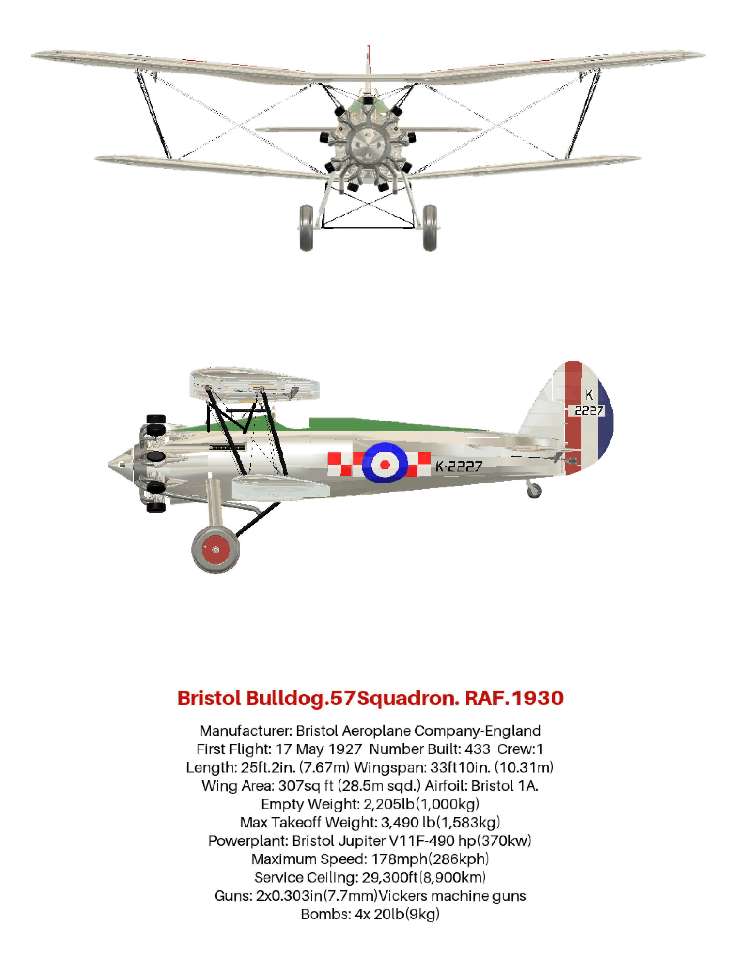 How the aviation art, of the Bristol Bulldog vintage biplane, was produced, using 3D software. Included are photos and links to many aviation gifts, from Zazzle
 -
Aviation gifts For All Airplane Lovers
Apr 20, 23 11:12 AM
 Aviation gifts for every occasion. Give your airplane fanatic friends and relatives the present they will really appreciate! Can be customized to make it truly unique.
 -
RC Retractable Landing Gear: The JP Hobby ER-005 Metal Strut Set.
Dec 19, 22 01:55 PM
 Full details of RC retractable landing gear. For models up to 6 Kg (13.2 lbs). Steerable nose wheel and sequencer for gear doors and brakes. For grass strips.
 -
FLEX RV-8 70CC FLS:ARF and ARFSV.
Nov 02, 22 02:45 PM
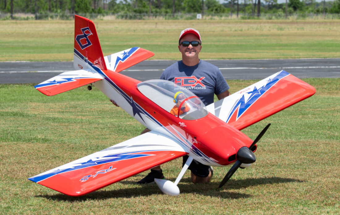 The Flex RV-8 70cc, 35% Scale, 3D RC Airplane. Super lightweight and gas or electric power. Very complete and fast assembly.