HOW TO INSTALL RC ENGINES
HINTS AND TIPS ON THE INSTALLATION OF RC ENGINES.
The installation of RC engines is a task that must be completed correctly or disaster can be the result! A solid, reliable mount must be built to ensure success and safety.
 Photo by hyper7pro (Johann Snyman)
The first step to take is to plan the installation and gather together all the components required. You will need the following-
- The Engine.
- A suitable muffler.
- The fuel tank.
- Engine mount.
- Engine mount hardware.
- Fuel tubing
- Fuel filter
- Fuel fill hardware.
Model Aircraft Mufflers

If the standard muffler will not fit your installation, then it is possible to find alternative suppliers who offer many alternatives.
Bisson Custom Mufflers have been around for quite a while and have an excellent reputation for good mufflers and a wide range of types to suit almost all 2-stroke RC engines.
The photo shows a 'Pitts Style" muffler. This type is excellent for a side mounted engine and an enclosed type of installation.
I have been using Bisson mufflers for many years and have never been disappointed with the results. Their mufflers are light weight and TIG welded into robust structures that will last a lifetime. Take a look at their website for full details. Bisson Custom Mufflers
Model Airplane Fuel Tanks

The size of the tank used for RC engines is usually recommended by the engine manufacturer. If you need to purchase a tank then I can strongly recommend Sullivan Products (Click here to visit their site) and Dubro Products. (Visit the site by clicking here). These suppliers offer a wide range of sizes and types of tanks. For a simple layout with an exposed or partially exposed engine then a two line tank system is possible. (As the Sullivan tank shown above) The bottom line has a weight fitting pushed on to the fuel feed line. This ensures the feed line is free to move around the tank and feed fuel to the engine carburetor what ever the position of the aircraft.
From the tank outlet the feed line will pass through the firewall and to the engine carburetor. Please make sure to install a fuel filter in this line on the engine side of the firewall.
The second line is the overflow line and muffler pressure line. Because the exposed engine is easily accessible the fuel lines can be removed from the carburetor and the muffler. The procedure for filling the tank is as follows-
- Remove both lines from the engine.
- Attach the fuel supply line to the fuel container.
- Pump fuel into the tank.
- When it is full, fuel will flow from the overflow line.
- Re-connect lines.
If the model features an exposed or partially exposed engine then the process is relatively simple. A fully enclosed engine takes a little more planning and a few tips picked up, over the years, by yours truly.
For an enclosed engine installation, where it is not possible to access the fuel lines then a third line is required. This is the tank fill line. Connect this line to a fuel fill device, such as a fuel dot or fuel fill valve.
It is a good idea to tie all connections with a miniature sized cable tie.
The Engine Mount

Most of the glow RC engines use a beam mount, consisting of mounting lugs, on each side of the crankcase.
Most kits include an engine mount, usually made of plastic. I much prefer an aluminum mount especially for rc engines larger than 0.40 cu.in. The local hobby shop should stock a good selection of engine mounts and you may decide to replace a metal mount with an aluminum one.
The first decision to make is regarding the position of the engine relative to the airframe. In some case a dimension is given from the firewall to the front face of the prop driver. (Usually for fully enclosed engines) If no dimension is given then you must decide for yourself where to place the engine. Make sure enough room is made for prop clearance and if you intend to use a spinner, ensure there is enough room for any clearance for the spinner back plate.
If using an aluminum mount then I prefer to use socket head cap screws to attach the engine to the mount. If a plastic mount is used then a high strength self tapping screw is used. In either case, make sure the correct core drill

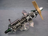
Another type of mount for RC engines is the stand-off type. The RC engines using this type of mount are generally the larger glow and gas RC engines. In these cases there are no mounting lugs, as in the beam mount, but a rear radial mount or back plate mount. The stand-offs are shown in red in the photo. These are manufactured from aluminum and are available in various lengths, generally from the engine manufacturer.
If the length is not available for your particular installation then it is possible to fabricate your own, using normal workshop tools.
Your local hardware store should stock all the components required. First you need to obtain 3/4 or 1 in. diameter dowel rod. Then you will need socket head cap screws of the correct length, for your particular installation. No 10-32 is generally the size required for most set-ups, but it depends on the hole diameter of your engine's mounting lugs. Don't forget the anchor nuts that have to be installed from the back of the firewall and also you will need eight "penny washers". These will be mounted at the front and back of each dowel stand-off.
Cut the dowel to the correct length and now drill a clearance hole through the center. This is best achieved by using a bench drill press, but it can be done using a hand drill and proceeding slowly and carefully.
The critical points to watch is that the hole through the dowel does not wander off center and that the ends of the dowel are sanded square and parallel to each other and all four are of the same length.
If the firewall does not incorporate the necessary side and down thrust angles, then the dowels must be of different lengths and front face angles. The best way to find these lengths and angles is to draw a simple layout using a protractor to lay out the recommended thrust offsets.
I have used this "home made" solution with great success in a number of installations of RC engines and can recommend it. The dowels must be "fuel proofed" and don't forget to use Locktite "Blue" on all screws.
Cowl installation
Many installations of RC engines use an engine cowl-especially scale models.
Cowls are generally manufactured from ABS plastic or fiberglass. If ABS is used then I like to add a layer of 2oz. fiberglass to the inside of the cowl. This adds considerably to the strength of the unit. Use epoxy resin and you should have no problem.
The next point to consider is the actual mounting of the cowl to the airframe. Some form of vibration isolation needs to be used. I have found that nylon washers under the cowl screw heads has helped. Another idea is to cut 1/4" lengths of fuel tubing, slip this over the cowl screws, with a washer under the screw head, and larger clearance holes in the cowl. This makes a good isolation mount when the screws are tightened down. The fuel tubing forms into a kind of grommet.It makes life a lot easier if the cowl mounting is done with the engine removed. The next challenge to overcome is to locate the position of the holes and cut-outs required for the engine. Some kits come with a second cowl made from a clear plastic. This makes the finding the position of holes etc., for RC engines, a lot simpler. Now you can see where the holes need to be for the needle valve, glow plug, etc. and can be marked on the clear cowl , using a felt tip marker. Now the holes and cut-outs can be made and checked. The clear cowl is now slipped over the final cowl and the hole positions transferred.Another method uses light card stock and a masking tape. Cut a strip of card about 1 in. wide. Start with the needle valve. Make a hole, in the card close to one end, big enough to give clearance for the valve or valve extension. Now slip the card over the needle valve and tape the card stock to the fuselage. Form a crease, so as the card can be folded back. Now slip the cowl into position. If the card is now unfolded then the position for the hole can be marked onto the cowl. Proceed slowly and carefully. Ensure there is adequate clearance, especially around mufflers and cylinder heads. A minimum of 1/8 in. is about correct.
General Notes on the Installation of RC Engines
Please ensure that all the components and fuel lines used in the system are compatible with the type of fuel used. Glow fuel components will dissolve in gasoline!
Once the installation is complete then all the wooden components must be fuel proofed. I prefer to mix up a batch of 30 minute epoxy and thin it about 50% with de-nurtured alcohol. (Available at most drug stores) Paint this mixture with a small disposable brush all over the firewall and all wooden parts to ensure a long life and prevent fuel from being absorbed.
The last point to consider is engine cooling. If the engine is enclosed then provision must be made to ensure that air can reach the cylinder head(s) and can exit the cowl. Bear in mind that exit area must be at least twice as large as the air entry area. Any baffles required to direct the air in a required direction can be made from 1/16 in. ply and epoxied to the inside of the cowl,
Please mention this website "RC-Airplanes-Simplified. com" if purchasing from any of the above recommended manufacturers websites.

Get Gloster Gladiator Profile eBook Free

Don't worry your e-mail address is totally secure.


Recent Articles
-
The Bristol Bulldog vintage biplane, of the RAF, in 1930
May 22, 23 10:47 AM
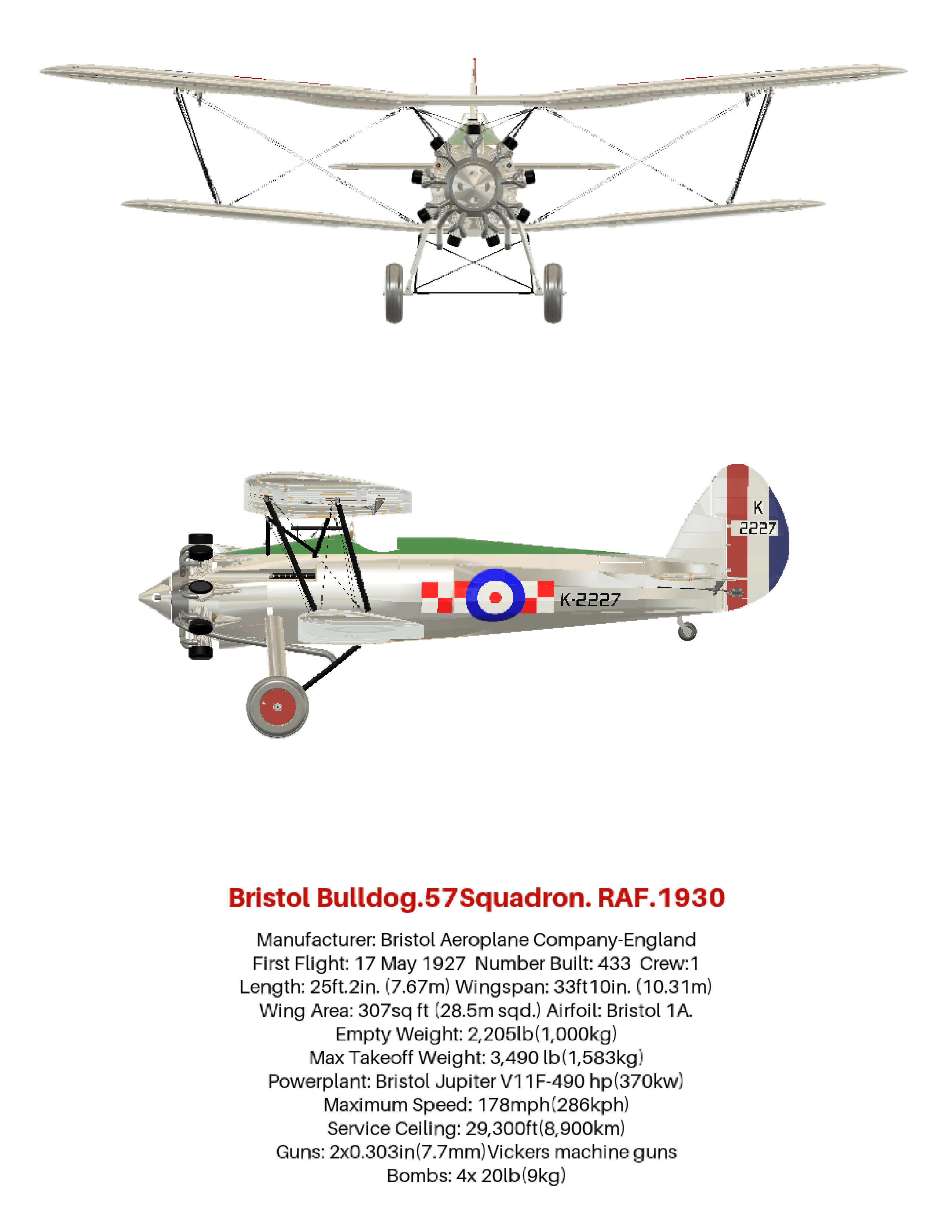 How the aviation art, of the Bristol Bulldog vintage biplane, was produced, using 3D software. Included are photos and links to many aviation gifts, from Zazzle
 -
Aviation gifts For All Airplane Lovers
Apr 20, 23 11:12 AM
 Aviation gifts for every occasion. Give your airplane fanatic friends and relatives the present they will really appreciate! Can be customized to make it truly unique.
 -
RC Retractable Landing Gear: The JP Hobby ER-005 Metal Strut Set.
Dec 19, 22 01:55 PM
 Full details of RC retractable landing gear. For models up to 6 Kg (13.2 lbs). Steerable nose wheel and sequencer for gear doors and brakes. For grass strips.
 -
FLEX RV-8 70CC FLS:ARF and ARFSV.
Nov 02, 22 02:45 PM
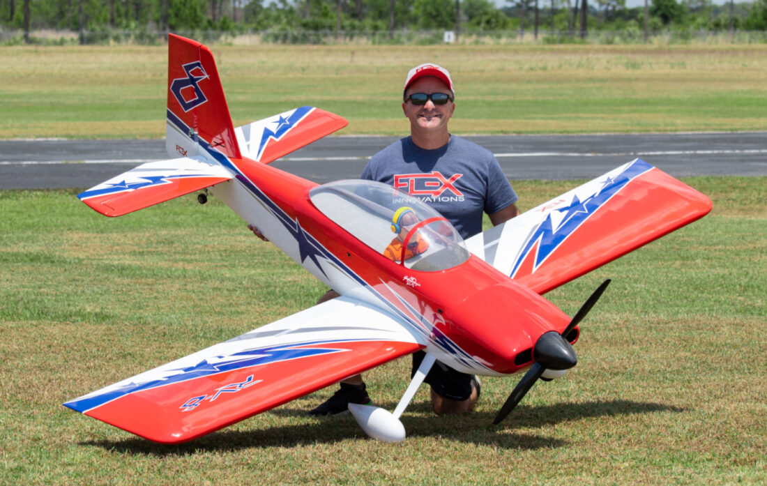 The Flex RV-8 70cc, 35% Scale, 3D RC Airplane. Super lightweight and gas or electric power. Very complete and fast assembly.
New! Comments
Have your say about what you just read! Leave me a comment in the box below.