RC Airplane Radios
RC Airplane radios, Tips on selecting the Right One for you.
 JR X9503 transmitter
A few words about the available FREQUENCIES of RC Airplane Radios.
Up until a short while ago, all RC airplane radios used exclusive frequencies in the 72 MHz range. 27 MHz was also available but was a crowded band that could lead to interference. Please note that the 50 assigned "spots" on the 72 MHz band are for EXCLUSIVE use by RC aircraft. Cars and boats have their own band in the 75 MHz band.
To make the situation even more difficult to understand, older radios were liable to "spread" over 2 or 3 frequency spots. In order to bring control over the situation clubs have a Frequency Control System.
This system, usually involving a peg or clip, ensures that a particular spot frequency is "blanked OFF" when the spot is in use. It should be pointed out that if two transmitters, on the same frequency are switched on at the same time then neither of the systems will function CORRECTLY!
The NUMBER ONE RULE of rc airplane radios is-CHECK THE FREQUENCY BEFORE SWITCHING ON THE TRANSMITTER!
If you are flying at a club field then please make absolutely sure you completely understand the frequency control system in use and follow it EXACTLY! If you are flying in a park or vacant lot, LOOK AROUND and if you see some one using an rc model then ASK them for the frequency they are using.
If your frequency is in use, then you must wait until it is clear before you turn on your transmitter. I personally always follow the club frequency system and prior to switching ON, watch any aircraft that are flying and am prepared to immediately switch OFF if something goes wrong.
The point to make is that an uncontrolled rc airplane is a highly dangerous missile, looking for a target! The rule is that if YOU cause a crash then you OWN IT! You are required to replace the damaged model, at your expense!
Now along comes a new technology in rc airplane radios that should make all of the above OBSOLETE! This new wonder is SPREAD SPECTRUM TECHNOLOGY.
Operating on the 2.4 GHz band this system is constantly "hopping" frequencies. I have heard of tests of 40 systems operating simultaneously with no problems! This system is also said to result in a very robust RF link-thus making the system almost immune to interference.
You can now have a unique RF link between transmitter and receiver-no more waiting for your frequency to become available!
However the old systems will remain with us for a while, so be prepared to deal with the situation in your particular area and always be safe!
If you are considering buying a new system then I strongly recommend you purchase a 2.4GHz radio. Of all the rc airplane radios available, this type of system has been around long enough to prove it's worth.
The Typical Radio System.
The typical system consists of-
- The Transmitter
- The Receiver
- The Servos
- The Battery
- The Switch.
1. The Transmitter.
The number of channels determines the layout of the transmitter. A three channel model has only one stick and a four (or more) channel has two sticks. Note that each control function is dedicated to a channel. For more information on the function of the sticks please refer to the page How to Fly RC Planes
The above photograph shows a seven channel, computerized transmitter. The term "computerized " tells us that this model features an internal microprocessor that controls the programming of the transmitter. This particular type has the ability to store up to twenty model programs. Each program is specific to a particular model, including all the trim settings.
2. The Receiver.
I am always amazed by how small a modern receiver is! These little electronic marvels can be mounted almost anywhere inside the fuselage. Please make sure it is secured correctly and mounted on foam rubber to isolate it from vibration. Ensure the antenna is routed correctly in as straight a line as possible. I have mounted my antennas internally in the fuselage for years and had no problems.
I use a length of nylon tubing (Usually a length of Nyrod) installed securely in the fuselage structure and thread the antenna through it.
3. The Servos.
Many sizes of servos are available. The smallest and lightest are used for indoor and park flyers. The medium or standard size are used for glow powered and electric models of a size up to those powered by a 0.60 cu.in. glow engine. They generally have a torque output of about 40 ozin. The next type to consider is the high torque servo used in the larger models. The size can be the same as the standard servo but torque can be up to 120 ozin.
For the Giant Scale Aerobatic aircraft capable of all the 3D maneuvers, multiple servos are used on each control surface. These must be coordinated with each other to ensure that one servo does not "fight" with another. Specialized electronics are available to allow correct synchronization.
A relatively new class of servo has recently been introduced, the high voltage/high torque servo. With a torque of 480 ozin. I doubt if multiples of these will be required!
The servos used in today's RC airplane radios are many and varied. Another difference is analog or digital. Analog was the original design, then along came digital that has much better resolution and holding power.
Coreless motors, ball bearings, metal gears. All these features and more are available. It all depends on the application and of course, how much money you are prepared to spend! When you consider that rc airplanes can range in size and speed, from micro-light indoor models to 200 MPH scale turbines, then it is possible to see why such a large range is offered by many manufacturers.
For the beginner, the standard servo with about 40 ozin of torque will prove adequate.
Regarding mounting servos in your model, first of all (and this applies to all parts of RC airplane radios), follow the manufacturers instructions! Ensure the mounting plate is robust and secure. if the mounting plate is 3mm lite ply (It usually is), then I re-enforce it with small ply tabs, beneath the servo mounting screws. Make sure the mounting ferrules are placed with the flange down (touching the plate) and do not over-tighten the screws. Remember we want to have a secure but vibration absorbing installation.
For more information on servos. visit this page-RC Servos. The Different types explained
4. The Battery.
The usual transmitter battery is a 9.6 volt NiCd or NiMh. These terms refer to the battery types. The NiCd or "nicad" has been around the longest and the NiMh or "nickel metal hydride" is the later and lighter technology found in rc airplane radios.
The onboard battery pack is generally of 4.8 volt size and can be either NiCd or NiMh type. An even newer technology is the LiPo (Lithium Polymer) type. This type is even lighter and is also used as the main battery in electric powered models.
It is also possible to use a 6.0 volt pack if extremely fast servo response is required but be careful! the receiver is probably rated for a 4.8 volt supply so a voltage regulator may be required. This higher voltage system is usually used in the large 3D aerobatic models or the very fast turbine powered jets.
What ever the type of battery employed please make sure the correct type of charger is used.
Of all the components in rc airplane radios, the battery pack is still the heaviest. Installing it in the model takes extra care and thought. Because it is relatively heavy it can be used to help balance the model. Usually it requires mounting as far forward as possible. Ensure that is isolated from vibration by mounting it in foam rubber (Not foam plastic).
To achieve balance, I sometimes mount the battery under the cowl. I first wrap the battery in foam rubber then put the package inside a plastic bag. This "package" is then tie wrapped to a suitable spot alongside the engine. Please make sure the installation is really secure! There is a lot of vibration at this location!
5. The Switch.
The switch is probably the most overlooked component in rc airplane radios. It is a vital part in a system. The quality of the switches used today, in most radios is adequate but if you have any misgivings then replace it with the highest quality switch you can find.
I personally prefer to use the JR switch and charge jack. This gives me dependability and the convenience of an external charging point. Always mount the switch, on the side of the fuselage away from the exhaust.
System Maintenance.
Modern RC airplane radios need very little maintenance. As long as they are mounted securely in a vibration resistant environment, long life should result. If you are unfortunate to crash your pride and joy and the reason for the accident appears to be a radio problem then please get it checked out by a reputable service center.
Before a flying session perform a range check. After ensuring your frequency is clear, switch on your system and check that all the controls are functioning correctly. Now walk 60 paces away and with the transmitter antenna collapsed, check again. If this will be the first flight of a new model then perform this test again with the engine running. If there appears to be any problems then do not fly until they are rectified.
Another installation tip is to keep all the plugs and sockets clean by wiping them with a soft rag dipped in alcohol. After assembling the plug and socket then wrap it with electrical insulation tape. This ensures the plugs will not separate.
Today's RC airplane radios are very reliable and should give you years of trouble free life and flying fun.

Get Gloster Gladiator Profile eBook Free

Don't worry your e-mail address is totally secure.


Recent Articles
-
The Bristol Bulldog vintage biplane, of the RAF, in 1930
May 22, 23 10:47 AM
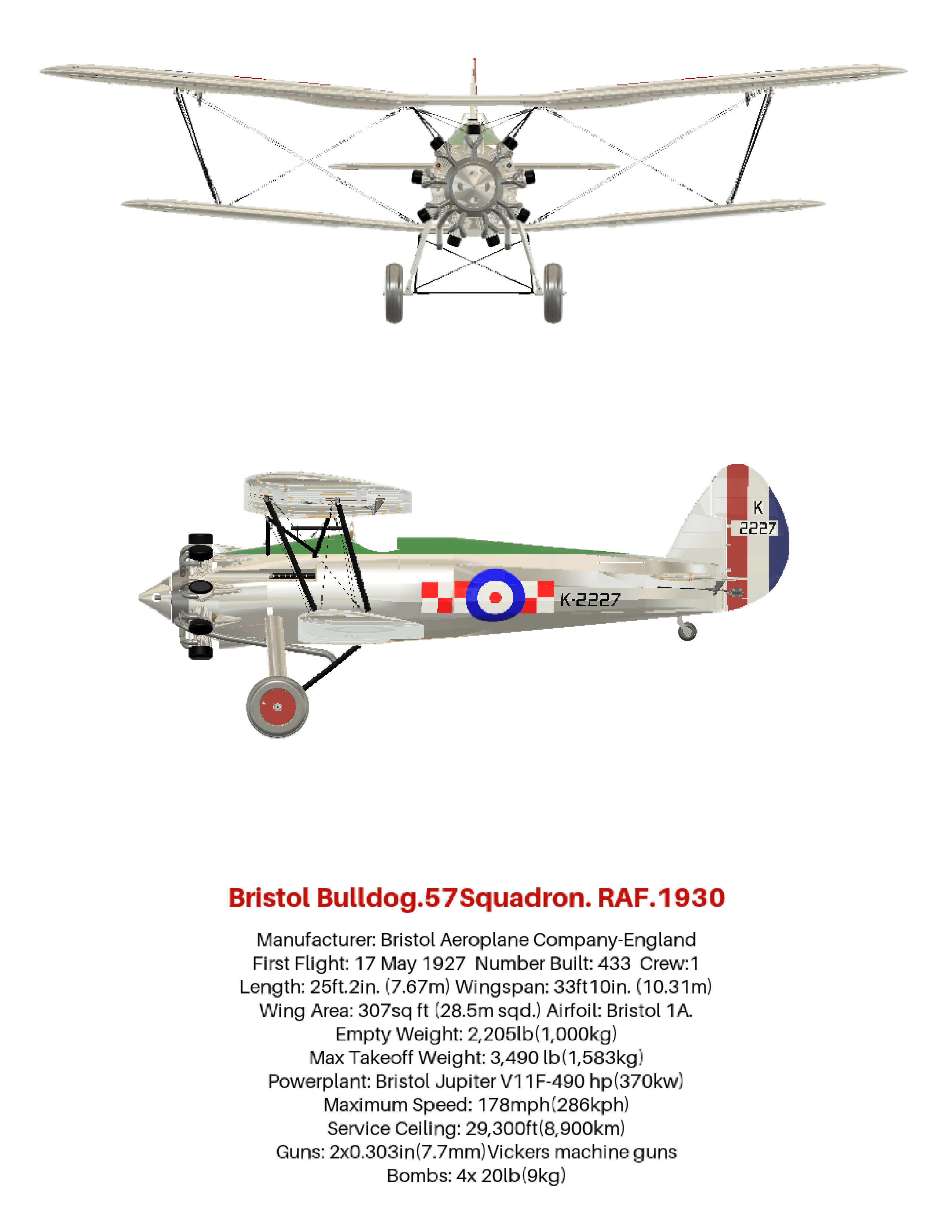 How the aviation art, of the Bristol Bulldog vintage biplane, was produced, using 3D software. Included are photos and links to many aviation gifts, from Zazzle
 -
Aviation gifts For All Airplane Lovers
Apr 20, 23 11:12 AM
 Aviation gifts for every occasion. Give your airplane fanatic friends and relatives the present they will really appreciate! Can be customized to make it truly unique.
 -
RC Retractable Landing Gear: The JP Hobby ER-005 Metal Strut Set.
Dec 19, 22 01:55 PM
 Full details of RC retractable landing gear. For models up to 6 Kg (13.2 lbs). Steerable nose wheel and sequencer for gear doors and brakes. For grass strips.
 -
FLEX RV-8 70CC FLS:ARF and ARFSV.
Nov 02, 22 02:45 PM
 The Flex RV-8 70cc, 35% Scale, 3D RC Airplane. Super lightweight and gas or electric power. Very complete and fast assembly.